
How to operate the three-roll calender equipment?
I. Application
A three-roll calender is used in conjunction with an extruder to calender products extruded from a sheet die, adjusting the product's thickness and surface finish to meet the required requirements. This allows for continuous production of plastic sheet products such as PE, PP, and PS in the desired width. Furthermore, by replacing the extruder and adjusting the die process, it can also achieve continuous production of SPVC, PE, PP, and PS sheets. This equipment features a novel structure, high automation, stable quality, easy production and maintenance, and smooth operation, making it a top choice for sheet product manufacturers.
II. Structure Overview
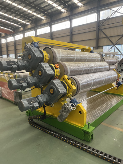
The three-roll calender equipment primarily consists of a mirror-finished calender, a transmission, a bracket, a base, a forward and reverse travel mechanism, a mold temperature controller, and an electrical control system.
The transmission is driven by a motor and a reduction gear system. The three rollers utilize a frequency converter for speed control, allowing for independent or synchronized adjustment.
The upper and lower rollers are mechanically clamped, ensuring precise positioning, excellent self-locking performance, and reliable stability. Constant temperature media is used within each roller to precisely control the temperature to meet the product's production process parameters. The equipment is driven forward and backward by a motor, and a deceleration system allows for product adjustment, making it convenient to adjust and disassemble molds during production. III. Main Technical Parameters
Roller Diameter: Ø450 x 1650 mm
Number of Rollers: 3
Roller Surface Quality (µm): Ra ≤ 0.25
Roller Hardness: (HRC) 50-55
Roller Chrome Plating: (µm): 40-50
Roller Pitch Adjustment Range (mm): 0-50
Roller Interface Thread Specification: Rc 1 1/2# Pipe Thread
Roller Heating Medium: Softened Water
Drive Motor Model: 90L4 Power: 1.5 kW
Drive Reducer Model: FAF77R37-1.5 kW
Output Speed: 5 rpm
Mechanical Clamp Reducer Model: NMRV75-0.75 kW-40/1
Clamping Motor Power: 0.75 kW-4
Number of Motor Reducers: 2
Cooling Water Pump Motor Power: 90L2 1.5 kW
Quantity: 3 Unit
Mobile Motor Power: 0.75 kW
Mobile Reducer Model: NRV63/50-D0.75-400/1
Quantity: 1 unit
External Dimensions (L x W x H): 1400 x 2400 x 2100 mm
Weight: 4000 kg
IV. three-roll calender equipment Installation
4.1. The machine should be installed on a solid surface. The foundation should be a concrete structure with a surface height of at least 80 mm.
4.2. When adjusting and tightening the machine, use a spirit level to level it. The level error should be less than 0.5%. The three rollers must be adjusted to their center height. The machine's footrest has four adjustment screws that adjust the machine's height according to the mold outlet height (the mold outlet must be leveled first). If the three-roll calender is fed from the bottom up, the lower edge of the middle roller should be aligned with the mold outlet. If the three-roll calender is fed from the top down, the upper edge of the middle roller should be aligned with the mold outlet. No further adjustments are required. 4.3. When laying electrical wiring on the three-roll calender and roller assembly, consider the possibility of movement. The electrical control devices are located on the main control station for the three-roll calender and traction unit.
4.4. While installing the unit, lay the power supply, air supply (compressed air at a minimum of 6 kg/cm²), and cooling water lines.
5. Trial Run
5.1. Manually move each transmission system to check for reliability and flexibility. Apply sufficient clean lubricant and then secure the unit with a safety cover.
5.2. Power on each component and check for reliable operation.
5.3. Conduct an air test to ensure coordinated operation and proper sealing of all pneumatic components.
5.4. Connect the mold temperature controller to test all piping for leakage.
5.5. After heating the mold, check whether the joints are tight or loose.
5.6. The gap between the three rolls is preliminarily adjusted before shipment. During shipment, the gap between the left and right rolls may become inconsistent. To adjust the rollers, first disconnect the couplings connecting the left and right ends. Place a copper feeler gauge between the lower and middle rollers, and between the upper and middle rollers, and then adjust the rollers up and down until the distance between the left and right ends is equal. After adjustment, close the couplings and tighten the set screws. Subsequent adjustment is generally not required.
5.7 Roller Opening and Closing
Move the roller raising and lowering buttons to check whether the rollers rise and fall in accordance with the button markings. If not, adjust the motor wiring.
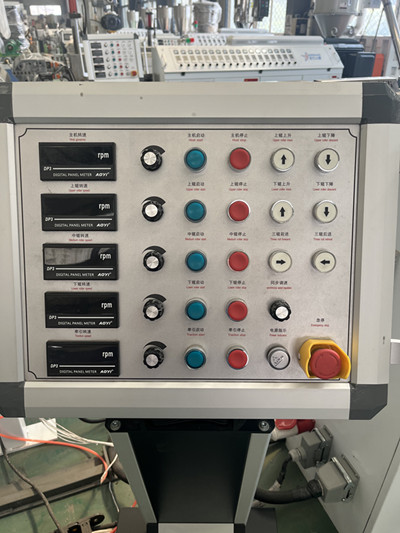
5.8 three-roll calender equipment Electrical
After checking the main power supply, check the following:
The roller rotation direction is adjusted before the machine leaves the factory. Depending on the feed method, the roller rotation direction can be divided into two types: bottom-in, top-out, and top-in, bottom-out. If the roller rotation direction differs from the diagram, adjust the motor wiring to match the diagram.
5.9 Three-Roller Temperature Adjustment
Start the three rollers and allow them to rotate slowly. Turn on the roller heating switch until the rollers reach the set temperature. Roller heating methods include water heating and oil heating, depending on the product. The temperature controller measures the roller temperature after the water (oil) exits the rollers.
5.10 Product Thickness Adjustment
With the material already discharged from the mold, press and hold the roller closing button and visually inspect the roller gap. When the rollers are about to reach the product thickness (depending on the product thickness and the worker's skill level, generally about 2 mm thicker than the product, but closer to the product thickness with increased skill), release the button and rotate the manual adjustment handle to continuously adjust the roller gap until the product reaches the desired thickness.
5.11 three-roll calender equipment Adjustment
Three-roller speed adjustment is closely related to the extruder's output and product specifications. The speed of each of the three rollers can be adjusted individually, simultaneously accelerated or decelerated (three-roller unified adjustment), or adjusted simultaneously across the entire production line (line unified adjustment). Adjustment steps: Adjust the speed of each roller individually → Adjust the speed of each roller collectively → Adjust the speed of the entire production line collectively. First, adjust the speeds of all three rolls to roughly the same level. Individual speed adjustments may be necessary based on the temperature differences between the three rolls. Then, perform a unified adjustment of all three rolls based on the amount of material accumulated between the rolls at the die outlet. Once the speed ratios for the entire production line are fully adjusted, increase the extruder output to complete the unified adjustment.
5.12. Keep detailed records of the test run, including the temperature, speed, and other parameters during normal production after adjustments, for future reference.


